AIM2006ModulesStrobes
From CNBH Acoustic Scale Wiki
This module finds strobe points (SP) in the individual channels of the NAP. These points correspond to maxima in the NAP pattern like those produced when glottal pulses excite the filterbank. The strobe pulses enable the segregation of the pulse and resonance information and they control pulse-rate normalisation. Auditory image construction is robust, in the sense that strobing does not have to occur exactly once per cycle to be effective, however, the most accurate representation of the resonance structure is produced with accurate, once-per-cycle strobing.
The default version of SP is sf2003
There are two different strobe modules available:
- sf1992: the original adaptive-thresholding version of strobing (peak_threshold)
- sf2003: this version has a more sophisticated version of adaptive thresholding.

Background
Perceptual research on pitch and timbre indicates that at least some of the fine-grain time-interval information in the NAP is preserved in the auditory image (e.g. Krumbholz, Patterson, Nobbe, & Fastl, 2003; Patterson, 1994a, 1994b; Yost et al., 1998). This means that auditory temporal integration cannot, in general, be simulated by a running temporal average process, since averaging over time destroys the temporal fine structure within the averaging window (Patterson et al., 1995). Patterson et al. (1992) argued that it is the fine-structure of periodic sounds that is preserved rather than the fine-structure of noises, and they showed that this information could be preserved by a) finding peaks in the neural activity as it flows from the cochlea, b) measuring time intervals from these strobe points to smaller peaks, and c) forming a histogram of the time-intervals, one for each channel of the filterbank. This two-stage temporal integration process is referred to as ‘strobed’ temporal integration (STI). It stabilizes and aligns the repeating neural patterns of periodic sounds like vowels and musical notes (Patterson, 1994a, 1994b; Patterson et al., 1995; Patterson et al., 1992). The complete array of interval histograms is AIM's simulation of our auditory image of the sound. The auditory image preserves all of the fine-structure of a periodic NAP if the mechanism strobes once per cycle on the largest peak (Patterson, 1994b; Patterson et al., 1992), and provided the image decays exponentially with a half life of about 30 ms, then it builds up and dies away with the sound as it should.
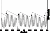
Aim2006 currently includes two strobe finding algorithms, sf1992 and sf2003. The older module, sf1992, operates on simple adaptive-filtering logic; it is included for demonstration purposes and to provide backward compatibility with previous versions of AIM. The newer strobe-finding module, sf2003, uses a more sophisticated adaptive thresholding mechanism to isolate strobe points. The process used by sf2003 is illustrated in Figure 9a, which shows one channel of the NAP, the adaptive threshold and strobe points; the centre frequency of the channel is 1.2 kHz. A strobe is issued when the NAP rises above the adaptive strobe-threshold; the strobe time is that associated with the peak of the NAP pulse. Following a strobe, threshold initially rises along a parabolic path and then returns to the linear decay to avoid spurious strobes. The duration of the parabola is given by the centre frequency of the channel; its height is proportional to the height of the strobe point. After the parabolic section of the adaptive threshold, its level decreases linearly to zero in 30 ms. The adaptive threshold and strobe points appear automatically when the single channel option is used with the SP display. Note that this simple mechanism locates one strobe per cycle of the vowel in this channel. Figures 9b and 9c show the strobe points located in all of the channels of each NAP in Figures 8a and 8b, for the gammachirp and gammatone filterbanks, respectively.
-110-122.jpg)
-256-122.jpg)
-110-89.jpg)
-256-89.jpg)
-110-122.jpg)
-256-122.jpg)
-110-89.jpg)
-256-89.jpg)